Falownik ABB ACSM1 PDF Drukuj

opis


alt


ACSM1 ABB  pretenduje do miana najbardziej uniwersalnych na rynku. Mogą one sterować pracą zarówno silników asynchronicznych jak i synchronicznych, w otwartej lub zamkniętej pętli sprzężenia zwrotnego. Dzięki temu użytkownik może wykorzystać jeden rodzaj napędu dla różnych typów silników elektrycznych określając tylko, jakie jest w danej aplikacji wymagane sprzężenie zwrotne.

Nowe, specjalistyczne napędy maszyn serii ACSM1 dostępne są dla zakresu mocy od 0,75 do 160 kW. Opierają się one o typową technologię wykorzystywaną w przemiennikach częstotliwości, ale dzięki zastosowaniu bardzo zaawansowanych algorytmów sterowania pozwalają osiągać wyniki znane do tej pory tylko dla serwonapędów.

Docelowymi użytkownikami nowych napędów są konstruktorzy maszyn i integratorzy zaawansowanych, precyzyjnych układów sterowania. Zakres aplikacji w których mogą być zastosowane ACSM1 jest niezwykle szeroki - znakomicie sprawdzą się w maszynach włókienniczych, ciągarkach/nawijarkach kabli, przenośnikach, w urządzeniach transportowych, w zautomatyzowanych magazynach, czy w układach cięcia w locie lub systemach wałów elektrycznych. W każdej z tych aplikacji ACSM1 mogą pracować jako sterowane prędkością lub momentem napędy serwo, współpracujące z nadrzędnym sterownikiem PLC lub w zdecentralizowanym układzie sterowania.


Powstanie przemienników częstotliwości serii ACSM1 to efekt czterech lat intensywnej pracy inżynierów Działu Rozwoju w fabryce ABB w Helsinkach (Finlandia). Podczas trwania tego projektu dogłębnie przeanalizowano i zoptymalizowano wszystkie aspekty nowego produktu, począwszy od technologii wytwarzania poszczególnych komponentów, poprzez opracowanie nowej konstrukcji i skończywszy na dalszym udoskonaleniu technologii napędów prądu przemiennego. Innowacje, które miały kluczowy wpływ na projektowanie nowego napędu to:

• Bezpośrednie Sterowanie Momentem (DTC)
• Szerszy wybór interfejsów sprzężenia zwrotnego
• Rozwój interfejsów magistral komunikacyjnych
• Przyjazna dla użytkownika, modułowa budowa
• Lepsza wydajność całego systemu napędowego


dane techniczne


Ratings Type code Frame size
P 1) *N kW P 1) hP '2N A / 31 2max A
0.75 1 2.5 5.3 ACSM1-04x4>x5|-02A5-4 A
1.1 1.5 3 6.3 ACSM1 -04x4>x5>-03A0-4 A
1.5 2 4 8.4 ACSM1 -04x4>x5>-04A0-4 A
2.2 3 5 10.5 ACSM1 -04x4»x5|-05A0-4 A
3 3 7 14.7 ACSM1 -04x4»x5'-07A0-4 A
4 5 9.5 16.6 ACSM1 -04x4)x5|-09A5-4 B
5.5 7.5 12 21 ACSM1-04x4>x5'-012A-4 B
7.5 10 16 28 ACSM1 -04x4»x5|-016A-4 B
11 15 24 42 ACSM1 -04x4»x5»-024A-4 C
15 20 31 54 ACSM1-04x4»x5|-031A-4 c
18.5 25 40 70 ACSM1 -04x4>x5>-040A-4 c
22 30 46 81 ACSM1 -04x4»x5'-046A-4 c
30 40 60 105 ACSM1-04x4»x5|-060A-4 D
37 50 73 128 ACSM1 -04x4)x5|-073A-4 D
45 60 90 150 ACSM1 -04x4)x5|-090A-4 D
55 75 110 165 ACSM1-04x4»x5i-110A-4 E
75 100 135 202 ACSM1 -04x4»x5|-135A-4 E
90 125 175 282 ACSM1-04x4>x5>-175A-4 E
110 150 210 326 ACSM1-04x4»x5|-210A-4 E


Feature / frame size A B C D E
Cutrent & Power          
Nominał current 2.5 to 7.0 A 9.5 to 16 A 24 to 46 A 60 to 90 A 110 to 210 A
Maximum current 5.3 to 14.7 A 16.6 to 28 A 42 to 81 A 105 to 158 A 165 to 326 A
Typical motor power 0.75 to 3 kW 4 to 7.5 kW 11 to22kW 30 to 45 kW 55 to 110 kW
Braking chopper
Braking resistor
Mains choke
Mains fiKer (EMC)
Mount i ng and cooling          
Removable power connectors     _ _ _
Removable control connectors #  
Air-cooled v ar i ant
- Back plate mounting
- DIN-rail mounting - - -
Cold plate variant - - -


charakterystyka


Bezpośrednie Sterowanie Momentem (DTC)

W ciągu ostatnich 10 lat, opracowane przez ABB
sterowanie DTC (Bezpośrednie Sterowanie Momentem)
osiągnęło powszechne uznanie wśród użytkowników
napędów w aplikacjach przemysłowych stając się wzorem
dla przemienników częstotliwości o najwyższych
parametrach pracy. Teraz DTC wykorzystano do
spełnienia wysokich wymagań producentów maszyn.
Sterowanie DTC dostosowano teraz do precyzyjnego
sterowania indukcyjnymi, synchronicznymi i
asynchronicznymi serwosilnikami przy zastosowaniu różnorodnych układów sprzężenia zwrotnego. DTC zapewnia bardzo szybką realizację pętli sprzężenia zwrotnego regulacji momentu, dzięki czemu uzyskuje się czasy zmiany momentu w zamkniętej pętli regulacji rzędu 62.5 do 250 µs. Są to osiągi zarezerwowane dla typowych aplikacji serwonapędów.
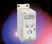
Rys. 1. ACSM1 w rozmiarze obudowy B.
Producenci maszyn często wymagają różnorodnych metod pozycjonowania i synchronizacji, włączając w to zcentralizowane jak i rozproszone systemy pozycjonowania. Specjalistyczne napędy maszyn ABB
zapewniają możliwość budowy obu rodzajów systemu. Z czasem reakcji 500 µs dla pozycjonowania i synchronizacji napędy ABB są odpowiednim rozwiązaniem dla większości bardzo wymagających aplikacji. Obsługa sygnałów zadawania jest konfigurowalna i zapewnia czasy od 250 µs dla optymalnych osiągów.

DTC - podstawowe cechy

Specjalistyczne napędy maszyn zachowują kluczowe cechy znane z innych produktów ABB takie jak sterowanie DTC oraz optymalizacja strumienia dla zapewnienia oszczędności energii. Czasem w złożonych aplikacjach jak np. maszyna papiernicza, tego typu funkcje nie są wymagane w napędzie głównym, jednak nie oznacza to, że ten sam produkt nie może być wykorzystany również w pomocniczych układach napędowych takich jak pompy czy wentylatory. Zaletą takiego rozwiązania dla użytkownika jest jednakowy interfejs sterowania, wspólne części zamienne, dokumentacja i szkolenia. Tradycyjne serwonapędy często nie są w stanie zapewnić takiej unifikacji, ponieważ ze względu na wymagany sygnał sprzężenia zwrotnego nie mogą sterować tradycyjnymi napędami pomp i wentylatorów.

W specjalistycznych napędach maszyn serii ACSM1 została zaimplementowana również funkcja lotnego startu. Zapewnia ona znakomite parametry pracy w układach otwartej jak i zamkniętej pętli regulacji poprawiając dodatkowo jakość i szybkość rozruchu. Ponadto, dzięki lepszej jakości regulacji momentu napęd szybciej odzyskuje pełną sterowalność po powrocie napięcia zasilającego. Lotny start jest istotny w ciągłych procesach produkcyjnych, gdy nawet krótka przerwa pracy może spowodować duże straty dla użytkownika.
Specjalistyczne napędy maszyn ABB posiadają wbudowane biblioteki różnorodnych bloków funkcyjnych filtrów. Filtry programowe są używane do dostrojenia sterowania silnikiem lub procesem w celu eliminacji lub redukcji mechanicznych wibracji oraz stabilizacji sygnału zadawania prędkości, momentu z zewnętrznego systemu.

Szeroki wybór interfejsów sprzężenia zwrotnego
Pomimo tego, że ACM1 zapewniają bardzo dobrą jakość regulacji pracując w układach z otwartą pętlą regulacji, to ze względu na uniwersalność zastosowania produktu,
wielu producentów maszyn oczekuje kompatybilności z różnymi układami sprzężenia zwrotnego, takimi jak enkodery absolutne, resolwery oraz “normalne” enkodery inkrementalne. Tak szeroki wybór elementów sprzężenia zwrotnego pozwala wyeliminować potencjalne problemy utraty pozycji przy zanikach zasilania w układach wykorzystujących enkodery absolutne. Dzięki temu są one lepiej dostosowane do pracy w złożonych aplikacjach maszynowych wymagających pozycjonowania i synchronizacji.
Jedną z najważniejszych cech wpływających na dokładność sterowania przy wykorzystaniu Bezpośredniego Sterowania Momentem (DTC) jest bardzo precyzyjny model matematyczny silnika tworzony w układach mikroprocesorowych wewnątrz napędu. W przypadku ACSM1 sygnał prędkościowego sprzężenia zwrotnego pochodzący od silnika może zostać użyty do udoskonalania tego modelu, dzięki czemu staje się on jeszcze bardziej precyzyjny i optymalny dla danej aplikacji.

Interfejsy magistral komunikacyjnych

Specjalistyczne napędy maszyn ABB mogą współpracować z nadrzędnymi układami sterowania poprzez bardzo efektywną komunikację w standardach PROFIBUS, CANopen, DeviceNet, EtherNet oraz Modbus. Interfejsy magistral komunikacyjnych są wyposażeniem opcjonalnym, co pozwala użytkownikowi na wybór odpowiedniego dla niego typu komunikacji. Każdy z tych modułów posiada własny mikroprocesor lub dedykowany układ scalony pozwalający na przetwarzanie sygnału na poziomie danego modułu. Obrobiony już sygnał jest przesyłany przez szybkie łącze wewnętrzne do głównego układu sterowania napędu. Napędy serii ACSM1 są także wyposażone w system próbkowania sygnałów Wej/Wyj, pozwalający zdefiniować inny czas próbkowania sygnałów każdego z Wej/Wyj a następnie zdefiniować ważność każdego z poziomów czasowych. Dzięki tym
rozwiązaniom mikroprocesor głównego układu sterowania napędu jest w mniejszym stopniu obciążany a jego wykorzystanie jest optymalizowane do aktualnych potrzeb.

Przyjazna dla użytkownika, modułowa budowa


Specjalistyczne napędy maszyn ABB zostały zaprojektowane w taki sposób, aby użytkownik mógł w chwili składania zamówienia dokładnie wyspecyfikować, jakie
funkcje programowe i opcje wyposażenia są dla niego najważniejsze a następnie dostał dokładnie to, czego potrzebuje. Opcje takie jak moduły rozszerzeń Wej/Wyj oraz interfejsy magistral komunikacyjnych czy sprzężenia zwrotnego są bardzo łatwe w montażu i w razie potrzeby mogą zostać zainstalowane u dystrybutora ABB, podczas kompletacji urządzenia lub u klienta końcowego.

Lepsza wydajność całego systemu napędowego

ABB opracowując napędy serii ACSM1 skupiło się na osiągnięciu lepszej wydajności całego systemu napędowego poprzez stworzenie bardzo szybkiego algorytmu przetwarzania sygnałów procesowych. Dzięki temu czas reakcji silnika na zmianę wartości zadanej, należy do najszybszych pośród produktów oferowanych na rynku. Hardware nowego napędu i jego oprogramowanie wewnętrzne zostały dobrane w taki sposób, aby optymalnie ze sobą współpracowały. Na przykład, jeśli czas zmiany prędkości w pętli regulacji wynosi 250 µs, to zarówno wszystkie Wej/Wyj jak i sygnał sprzężenia zwrotnego z enkodera będą równe 250 µs. W żadnym z elementów napędu nie będzie opóźnienia w przetwarzaniu sygnału zadawania.


alarmy


Code Alarm (fieldbus code) Cause What to do
2000 BRAKE START TOROUE (0xFF74) Programmable fault: 35.09 BRAKE FAULT FUNC Mechanlcal brake alarm. Alarm is activated if required motor startlng torque, 35.06 BRAKE OPEN TORO, is not achieved. Check brake open torque setting, parameter 35.06. Check drive torque and current limits. See firmware błock LIMITS on page 82.
2001 BRAKE NOT CLOSED (0xFF75) Programmable fault: 35.09 BRAKE FAULT FUNC Mechanlcal brake control alarm. Alarm is activated eg. if brake acknowledgement is not as expected during brake closing. Check mechanical brake connection. Check mechanical brake settings, parameters 35.01...35.09. To determine whether problem is with acknowledgement signal or brake: Check if brake is closed or open.
2002 BRAKE NOTOPEN (0xFF76) Programmable fault: 35.09 BRAKE FAULT FUNC Mechanlcal brake control alarm. Alarm is activated eg. if brake acknowledgement is not as expected during brake opening. Check mechanical brake connection. Check mechanical brake settings. parameters 35.01...35.08. To determine whether problem is with acknowledgement signal or brake: Check if brake is closed or open.
2003 SAFE TOROUE OFF (0xFF7A) Programmable fault: 46.07 STO DIAGNOSTIC Safe Torque Off function is active, i.e. safety circuit signal(s) connected to connector X6 is lost while drive is stopped and parameter46.07 STO DIAGNOSTIC setting is ALARM. Check safety circuit connectjons. For more Information, see appropriate dhve hardware manuał.
2004 STO MODE CHANGE (0xFF7D) Error in changing Safe Torque Off supen/ision, i.e. parameter 46.07 STO DIAGNOSTIC setting could not be changed to value ALARM. Contact your local ABB representative.
2005 MOTOR TEMPERATURĘ (0x4380) Programmable fault: 45.01 MOT TEMP PROT Estimated motor temperaturę (based on motorthermal model) has exceeded alarm limit defined by parameter 45.03 MOT TEMP ALM LIM. Check motor ratings and load. Let motor cool down. Ensure proper motor cooling: Check cooling fan, clean cooling surfaces. etc. Check value of alarm limit. Check motor thermal model settings, parameters 45.06...45.08 and 45.10 MOT THERM TIME.
    Measured motor temperaturę has exceeded alarm limit defined by parameter 45.03 MOT TEMP ALM LIM. Check that actual number of sensors corresponds to value set by parameter 45.02 MOT TEMP SOURCE. Check motor ratings and load. Let motor cool down. Ensure proper motor cooling: Check cooling fan, clean cooling surfaces, etc. Check value of alarm limit.
2006 EMERGENCY OFF (0xFF90) Drive has received emergency OFF2 command. To restart dhve, activate RUN ENABLE signal (source selected by parameter 10.09 RUN ENABLE) and start drive.
2007 RUN ENABLE (0xFF91) No Run enable signal is received. Check setting of parameter 10.09 RUN ENABLE Switch signal on or check wihng of selected source.
2008 ID-RUN (0xFF84) Motor Identification run is on. This alami belongs to normal start-up procedurę. Wart until drive indicates that motor identification is completed.
    Motor Identification is required. This alarm belongs to normal start-up procedurę. Select how motor identification should be periormed, parameter 99.13 ID RUN MODE. Start identification routines by pressing Start key.
2009 EMERGENCY STOP (0xFF92) Drive has received emergency stop command {OFF1/OFF3). Check that it is safe to continue operation. Return emergency stop push button to normal positjon. Restart drive.
2011 BR OVERHEAT (0x7112) Brake resistor temperaturę has exceeded alarm limit defined by parameter 48.07 BR TEMP ALARM LIM. Stop drive. Let resistor cool down. Check resistor overload protection function settings, parameters 48.03.. .48.05. Check alarm limit setting, parameter 48.07. Check that braking cycle meets allowed limits.
2012 BC OVERHEAT (0x7181) Brake chopper IGBT temperaturę has exceeded internal alarm limit. Let chopper cool down. Check resistor overload protection function settings, parameters 48.03.. .48.05. Check that braking cycle meets allowed limits. Check that drive supply AC voltage is not excessive.
2013 DEVICE OVERTEMP (0x4210) Measured drive temperaturę has exceeded internal alarm limit. Check ambient conditions. Check airflow and fan operation. Check heatsink fins for dust pick-up. Check motor power against unit power.
2014 INTBOARD OVERTEMP (0x7182) interiace board (between power unit and control unit) temperaturę has exceeded internal alarm limit. Letdrive cool down.
2015 BC MODOVERTEMP (0x7183) input bhdge or brake chopper temperaturę has exceeded internal alarm limit. Let drive cool down.
2016 IGBT OVERTEMP (0x7184) Drive temperaturę based on thermal model has exceeded internal alarm limit. Check ambient conditions. Check airfiow and fan operation. Check heatsink fins for dust pick-up. Check motor power against unit power
2017 FIELDBUS COMM (0x7510) Programmable fault: 50.02 COMM LOSS FUNC Cyclical communication between drive and fieldbus adapter module or between PLC and fieldbus adapter module is lost. Ch^ck status of fieldbus communication. See approphate User s Manuał of fieldbus adapter module. Check fieldbus parameter settings. See firmware błock FIELDBUS on page 141. Check cable connections. Check if communication master can communicate.
2018 LOCAL CTRL LOSS (0x5300) Programmable fault: 46.03 LOCAL CTRL LOSS Control panel or PC tool selected as active control location for drive has ceased communicating. Check PC tool or control panel connection. Check control panel connector. Replace control panel in mounting platform.
2019 Al SUPERVISION (0x8110) Programmable fault: 13.12 Al SUPRVISION AnalogueinputAM orAI2slgnal has reached limit defined by parameterl3.13AI SUPERVIS ACT Check analogue input AU/2 source and connections. Check analogue input AU/2 minimum and maximum limit settings. parameters 13.02 and 13.03/13.07 and 13.08.
2022 ENCODER 1 FAILURE (0x7301) Encoder 1 has been activated by parameter but the encoder interface (FEN-xx) cannot be found. Check parameter 90.01 ENCODER 1 SEL setting corresponds to encoder interface 1 (FEN-xx) installed in drive Slot 1/2 {signal 9.20 OPTION SLOT 1 / 9.21 OPTION SLOT 2). Note: The new setting will only take effect after parameter 90.10 ENC PAR REFRESH is used or after the JCU control unit is powered up the next time.
2023 ENCODER 2 FAILURE (0x7381) Encoder 2 has been activated by parameler but the encoder interface (FEN-xx) cannot be found. Check parameter 90.02 ENCODER 2 SEL setting corresponds to encoder interface 2 (FEN-xx) installed In drive Slot 1/2 (slgnal 9.20 OPTION SLOT 1 / 9.21 OPTION SLOT 2). Note: The new setting will only take effect after parameter 90.10 ENC PAR REFRESH is used or after the JCU control unit is powered upthenext time.
EnDat or SSI encoder is used In continuous mode as encoder 2. [I.e. 90.02 ENCODER 2 SEL = FEN-11 ABS and 91 02 ABS ENC INTERF = EnDat (or 91.02 ABS ENC INTERF = SSI) and 91.30 ENDAT MODE = CONTINUOUS {or 91.25 SSI MODE = CONTINUOUS).] If possible, use single position transfer instead of continuous position transfer (i.e. if encoder has incremental sin/cos signals): - Change parameter 91.25 SSI MODE / 91.30 ENDAT MODE to value INITIAL POS. Otherwise use EndatfSSI encoder as encoder1: -Change parameter 90.01 ENCODER 1 SEL to value FEN-11 ABS and parameter 90.02 ENCODER 2 SEL to value NONE Note: The new setting will only take effect after parameter 90.10 ENC PAR REFRESH is used or after the JCU control unit is powered upthe nexttime.
2026 ENC EMULATION FAILURE (0x7384) Encoder emulation error If position value used in emulation is measured by encoder: - Check that FEN-xx encoder used in emulation (90.03 EMUL MODE SEL) corresponds to FEN-xx encoder interface 1 or (and) 2 activated by parameter 90.01/90.02 ENCODER 1/2. (Parameter 90.01/90.02 activates the position calculation of the used FEN-xx input). if position value used in emulation is determined by drive software: - Check that FEN-xx encoder used in emulation (90.03 EMUL MODE SEL) corresponds to FEN-xx encoder interface 1 or (and) 2 activated by parameter 90.01/90.02 ENCODER 1/2 (because position data used in emulation is written to FEN-xx during encoder data request). Encoder interface 2 is recommended. Note: The new setting will only take effect after parameter 90.10 ENC PAR REFRESH is used or after the JCU control unit is powered upthenext time.
2027 FEN TEMP MEAS FA1LURE (0x7385) Error in temperaturę measurement when temperaturę sensor (KTY or PTC) connected to encoder interface FEN-xx is used. Check mat parameter 45.02 MOT TEMP SOURCE settings correspond to encoder interface installation (9.20 OPTION SLOT 1 / 9.21 OPTION SLOT 2): If one FEN-xx module is used: - Parameter 45.02 MOT TEMP SOURCE setting must be either KTY ist FEN or PTC ist FEN. FEN-xx module can be in either Slot 1 or Slot 2. If two FEN-xx modules are used: - When parameter 45.02 MOT TEMP SOURCE setting is KTY 1st FEN or PTC 1st FEN, me encoder installed in dhve Slot 1 is used. - When parameter 45.02 MOT TEMP SOURCE setting is KTY 2nd FEN or PTC 2nd FEN, me encoder installed in drive Slot 2 is used.
    Error in temperaturę measurement when KTY sensor connected to encoder interface FEN-01 is used. FEN-01 does not support temperaturę measurement with KTY sensor. Use PTC sensor or other encoder interface module.
2028 ENC EMUL MAX FREQ (0x7386) TTL pulse frequency used in encoder emulation .exceeds maximum aliowed limit (500 kHz). Decrease parameter 93.21 EMUL PULSE NR value. Note: The new setting will only take effect after parameter 90.10 ENC PAR REFRESH is used or after the JCU control unit is powered up the next time.
2029 ENC EMUL REF ERROR (0x7387) Encoder emulation has failed due to failure in wńting new fposition) reference for emulation. Contact your local ABB representative.
2030 RESOLVER AUTOTUNE ERR (0x7388) Resolver autotuning routines, which are automatically started when resolver input is activated for the first time, have failed. Check cable between resolver and resolver interface module (FEN-21) and order of connector signal wires at both ends of cable. Check resolver parameter settings. For resolver parameters and Information, see firmware błock RESOLVER CONF on page 172. Note: Resolver autotuning routines should always be performed after resolver cable connection has been modified. Autotuning routines can be activated by setting parameter 92.02 EXC SIGNAL AMPL or 92.03 EXC SIGNAL FREQ. and then setting parameter 90.10 ENC PAR REFRESH to 1.
2031 ENCODER 1 CABLE (0x7389) Encoder 1 cabie fault detected. Check cable between FEN-xx interface and encoder 1. After any modifications in cabling, re-configure interface by swltchlng drive power off and on, or by activating parameter 90.10 ENC PAR REFRESH.
2032 ENCODER 2 CABLE (0x73SA) Encoder 2 cable fault detected. Check cable between FEN-xx interface and encoder 2. After any modifications in cabling, re-configure interface by switchlng drive power off and on, or by activating parameter 90.10 ENC PAR REFRESH.
2033 D2D COMMUNICATION (0x7511) Programmable fault: 57.02 COMM LOSS FUNC Drive-to-drive communication break detected. Check the drive-to-drive cabling.


błędy


Code Fault (fieldbus code) Cause What to do
0001 OVERCURRENT (0x2310) Output current has exceeded internal fault limit. Check motor load. Check acceleration time. See firmware błock SPEED REF RAMP on page 96. Check motor and motor cable {including phasing and delta/star connection). Check that the start-up data in parameter group 99 corresponds to the motor rating plate. Check that there are no power factor correction capacitors or surge absorbers in motor cable. Check encoder cable (including phasing).
0002 DC OVERVOLTAGE (0x3210) Excessive intermediate circuit DC voltage Check that overvoltage controller is on, parameter 47.01 OVERVOLTAGE CTRL. Check mains for static or transient overvoltage. Check brake chopper and resistor (if used). Check deceleration time. Use coast-to-stop function (if applicable). Retrofit frequency converter with brake chopper and brake resistor
0003 DEVICE OVERTEMP (0x4210) Measured drtve temperaturę has exceeded internal fault limit. Check ambient conditions. Check air flow and fan operation. Check heatsinK fins for dust pick-up. Check motor power against unit power
0004 SHORT CIRCUIT (0x2340) Short-circuit In motor cable(s) or motor Check motor and motor cable. Check there are no power factor correction capacitors or surge absorbers in motor cable.
0005 DC UNDERVOLTAGE (0x3220) Intermediate circuit DC voltage is not sufficient due to missing mains phase, blown fuse or rectifier bridge internal fault. Check mains supply and fuses.
0006 EARTH FAULT (0x2330) Drive has detected load unbalance typically due to earth fault in motor or motor cable. Check there are no power factor correction capacitors or surge absorbers in motor cable. Check that there is no earth fault in motor or motor cables: - measure insulation resistances of motor and motor cable. if no earth fault can be detected, contact your local ABB representative.
0007 FAN FAULT (0xFF83) Fan is not able to rotate freely or fan is disconnected. Fan operation is monitored by measuring fan current. Check fan operation and connection.
0008 IGBT OVERTEMP (0x7184) Drive temperaturę based on thermal model has exceeded internal fault limit. Check ambient conditions. Check airflow and fan operation. Check heatsink fins for dust pick-up. Check motor power against unit power.
0009 BCWIRING (0x7111) Brake resistor short circuit or brake chopper control fault Check brake chopper and brake resistor connection. Ensure brake resistor is not damaged.
0010 BCSHORT CIRCUIT (0x7113) Short circuit in brake chopper IGBT Replace brake chopper. Ensure brake resistor is connected and not damaged.
0011 BC OVERHEAT (0x7181) Brake chopper IGBT temperaturę has exceeded internal fault limit. Let chopper cool down. Check resistor overload protection function settings, parameters 48.03.. .48.05. Check that braking cycle meets allowed limits. Check that dhve supply AC voltage is not excessive.
0012 BR OVERHEAT (0x7112) Brake resistor temperaturę has exceeded fault limit defined by parameter 48.06 BR TEMP FAULTLIM. Stop drive. Let resistor cool down. Check resistor overload protection function settings, parameters 48.03.. .48.05. Check fault limit setting, parameter 48.06. Check that braking cycle meets allowed limits.
0013 CURR MEAS GAIN (0x3183) Difference between output phase U2 and W2 current measurement gain is too great. Contact your local ABB representative.
0014 CABLE CROSS CON (0x3181) Programmable fault: 46.08 CROSS CONNECTION incorrect input power and motor cable connection (i.e. input power cable is connected to drive motor connection). Check input power connections.
0015 SUPPLY PHASE (0x3130) Programmable fault: 46.06 SUPPL PHS LOSS. intermediate circuit DC voltage is oscillating due to missing input power line phase or blown fuse. Check input power line fuses. Check for input power supply imbalance.
0016 MOTOR PHASE (0x3182) Programmable fault: 46.04 MOT PHASE LOSS Motor circuit fault due to missing motor connection (all three phases are not connected). Connect motor cable.
0017 ID-RUN FAULT (0xFF84) Motor ID Run is not completed successfully. Check motor settings, parameters 99.04...99.13. Check that no limits prevent ID run Following must apply: 20.05 MAXIMUM CURRENT > 99.06 MOT NOM CURRENT for Reduced and Normal ID run: - 20.01 MAXIMUM SPEED > 55% of 99.09 MOT NOM SPEED - 20.02 MINIMUM SPEED 65% of 99.07 MOT NOM VOLTAGE -20.06 MAXIMUM TORGUE > 100% (onlyfor Normal ID ain}. Retry.
0018 CURR U2 MEAS (0x3184) Measured offset error of U2 output phase current measurement is too great. (Offset value is updated during current calibratjon.) Contact your local ABB representative.
0019 CURR V2 MEAS (0x3185) Measured offset error of V2 output phase current measurement is too great (Offset value is updated during current calibratjon.) Contact your local ABB representative.
0020 CURR W2 MEAS (0x3186) Measured offset error of W2 output phase current measurement is too great. (Offset value is updated during current calibratjon.) Contact your local ABB representative.
0021 ST01 LOST (0xFF7B) Safe Torque Off function is active, i.e. safety circuit signal 1 connected between X6:1 and X6:3 is lost while drive is at stopped state and parameter 46.07 STO DIAGNOSTIC setting is ALARM or NO. Check safety circuit connections. For more Information, see appropriate drive hardware manuał.
0022 ST02 LOST (0xFF7C) Safe Torque Off function is actrve, i.e. safety circuit signal 2 connected between X6:2 and X6:4 is lost while drive is at stopped state and parameter 46.07 STO DIAGNOSTIC setting is ALARM or NO. Check safety circuit connections. For more Information, see appropriate drive hardware manuał.
0023 STO MODE CHANGE (0xFF7D) Error in changing Safe Torque Off supen/ision, i.e. parameter 46.07 STO DIAGNOSTIC setting could not be changed to value FAULT Contact your local ABB representative.
0024 INTBOARD OVERTEMP (0x7182) inferface board (between power unit and control unit) temperaturę has exceeded internal fault limit. Letdrive cool down.
0025 BC MOD OVERTEMP (0x7183) input bridge or brake chopper temperaturę has exceeded internal fault limit. Letdrive cool down.
0030 EXTERNAL (0x9000) Fault in extemal device. (This Information is configured through one of programmable digital inputs.) Check external devices forfaults. Check parameter 46.01 EXTERNAL FAULT setting.
0031 SAFE TOROUEOFF (0xFF7A) Programmable fault; 46.07 STO DIAGNOSTIC Safe Torgue Off function is active, i.e. safety circuit signal(s) connected to connectorX6 is lost - during drive start or drive run or - while drive is stopped and parameter 46.07 STO DIAGNOSTIC setting is FAULT Check safety circuit connections. For more information. see appropriate drive hardware manuał.
     
0032 OVERSPEED (0x7310) Motor is turning faster than highest allowed speed due to incorrectly set minimum/ maximum speed, insufficient braKing torque or changes in load when using torque reference. Check minimum/maximum speed settings. parameters 20.01 MAXIMUM SPEED and 20.02 MINIMUM SPEED. Check adequacy of motor braking torque. Check applicability of torque control. Check need for brake chopper and resistor(s).
0033 BRAKE START TORGUE (0xFF74) Programmable fault: 35.09 BRAKEFAULT FUNC Mechanical brake fault. Fault is activated if required motor starting torgue, 35.06 BRAKE OPEN TORO, is not achieved. Check brake open Iorque setting, parameter 35.06. Check drive torque and current limits. See firmware błock LIMITS on page 82.
0034 BRAKE NOT CLOSED (0xFF75) Programmable fault: 35.09 BRAKE FAULT FUNC Mechanical brake control fault. Fault is activated if brake acknowledgement is not as expected during brake closing. Check mechanical brake connection. Check mechanical brake settings, parameters 35.01...35.09. To determine whether problem is with acknowledgement signal or brake: Check if brake is closed or open.
0035 BRAKE NOTOPEN (0xFF76) Programmable fault: 35.09 BRAKEFAULT FUNC Mechanical brake control fault. Fault is activated if brake acknowledgement is not as expected during brake opening Check mechanical brake connection. Check mechanical brake settings, parameters 35.01...35.08. To determine whether problem is with acknowledgement signal or brake: Check if brake is closed or open.
0036 LOCAL CTRL LOSS (0x5300) Programmable fault: 46.03 LOCAL CTRL LOSS Control panel or PC tool selected as active control location for drive has ceased communicating. Check PC tool or control panel connection. Check control panel connector. Replace control panel in mounting platform.
0037 NVMEMCORRUPTED (0x6320) Drive intemal fault Note: This fault cannot be reset. Contact your local ABB representative.
0038 OPTION COMM LOSS (0x7000) Communication between drive and option module (FEN-xx and/or FIO-xx) is lost Check that option modules are properly connected to Slot 1 and (or) Slot 2. Check that option modules or Slot 1/2 connectors are not damaged. To determine whether module or connector is damaged: Test each module individually in Slot 1 and Slot 2.


Dystrybutor ABB

W sprawie publikacji danych dystrybutora prosimy o kontakt :

Warto zobaczyć

Reklama
Kupując falownik
 
dobór falowniki Wortal napędów energoelektronicznych www.falowniki.pi . Napędy energoelektroniczne do regulacji prędkości obrotowej silników elektrycznych.

Copyright © 2010 www.falowniki.pl